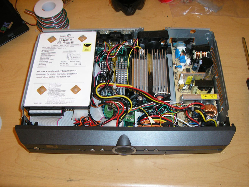
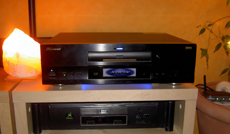
Xbox converted to Stereo Component with LCD display
From falz.net
I originally purchased an Xbox with the only intent of having it as a media playing device. A few months after the modchips became mainstream, I picked one up (summer 2002 I *think*). Shortly after this the first MP3 playing software for the Xbox was a demo app by Frodo. A few months after, his code was merged into some others and became Xbox Media Player (XBMP). Since then this has evolved into Xbox Media Center (XBMC) and supports justa bout every audio and video format, and has many keen features such as LCD support and a million other things.
When I got my Xbox, I did so with the intention of transplanting it into a CD player type of case so it can sit with other stereo components and not look like ass. I posted on the xbox-scene.com forums about this, and the general response is that it was stupid.
I got a few broken CD players, but the components wouldn't fit quite right without extensive modification to the case. Also, I would have to somehow get a machined front panel that doesn't look like butt.
So, the idea was shelved.
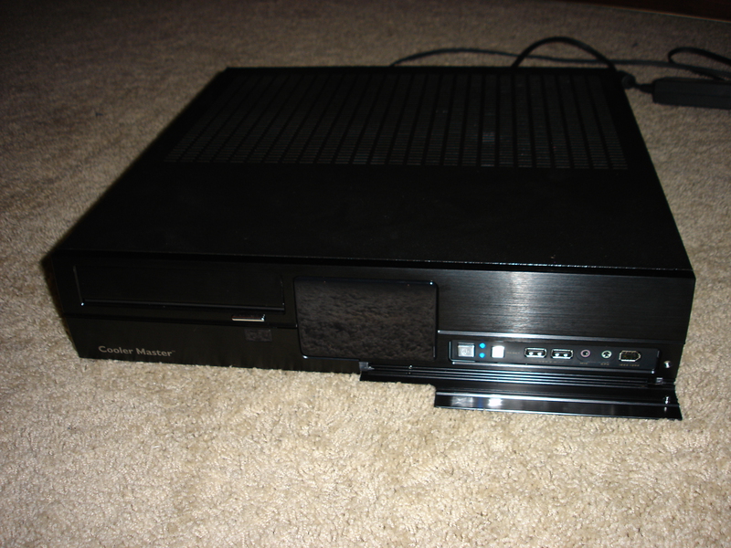
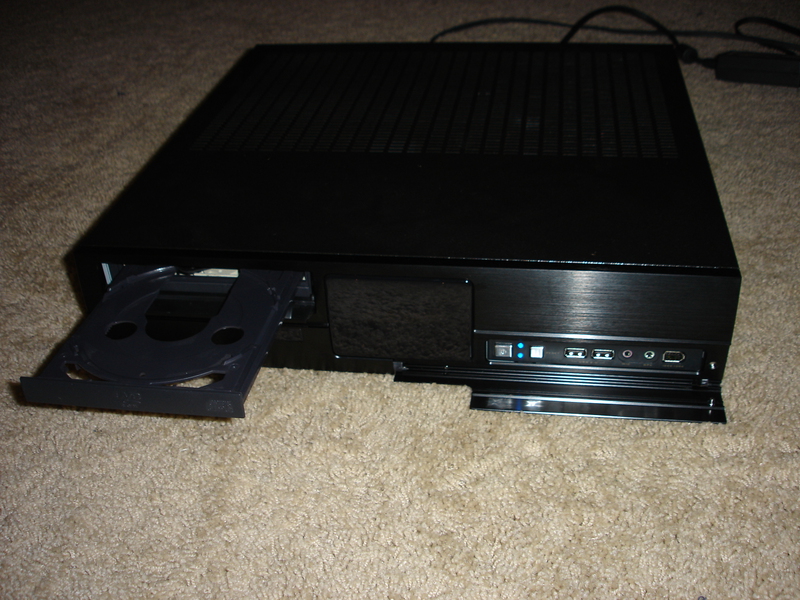
I was browsing Newegg ([1]) and home theater component looking PC cases have become much more mainstream since then. One in particular was cheap, looked decent (minus the "Cooler Master" logo on the front) and was about the correct size. The Cooler Master CM Media 260, which was $80 (ed: I just noticed it's now $55!):
Components Used
- Case - (Cooler Master CM Media 260)
- Modchip - I originally had a PC-Bioxx chip. Since then I've got a simple cheapmod-based Aladdin chip.
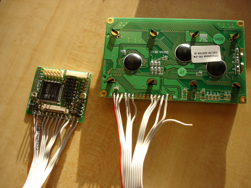
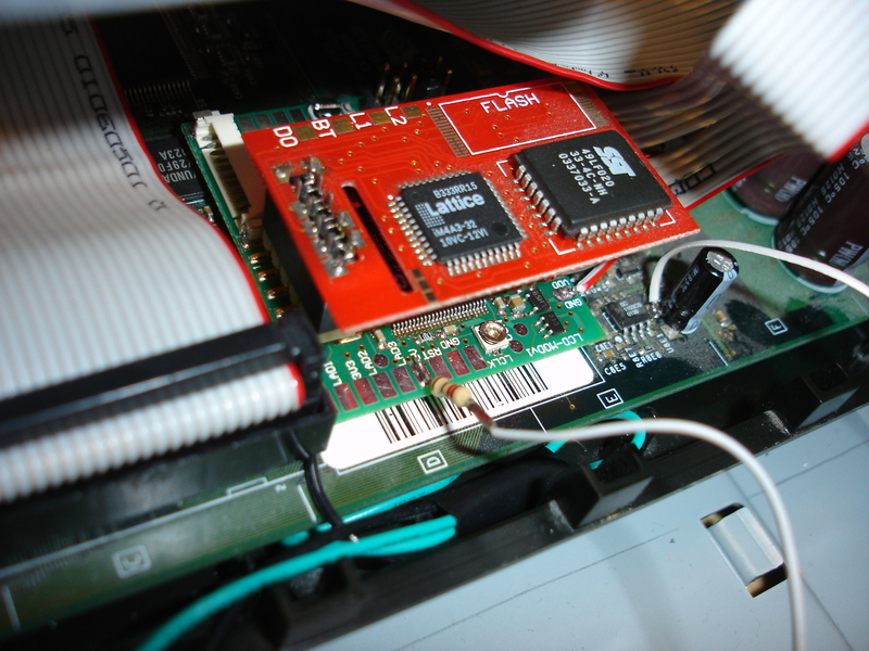
- LCD Modchip - Since Ive already had a modchip, there was no reason to get an X3 or SmartXX or any of the other modchips that have the native SPI and/or Parallel bus support. I picked up an LCD-MOD which simply adds the interface(s) needed to talk to an LCD. This sits in between the Aladdin and the Xbox's LPC headers.
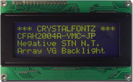
- LCD - Most information out there for LCD's leads you to the X3 LCD modchip + LCD Panel, or the entire replacement front panel. The X3 LCD has a blue background with lighter text, which is bizarro world in my opinion- I want my text to be light, background black, like any standard stereo component. So, I did some research. It looks like any LCD that has the HD44780 chip and a 4-bit bus should work just fine. I ended up ordering a CrystalFontz CFAH2004A-YMC-JP.
- X3IR - Required if you'd like to turn on/off your xbox via IR. I chose this one because the remote codes are programmable, and you don't have to use stupid combos (such as pressing a single button 3 times) to turn it off.
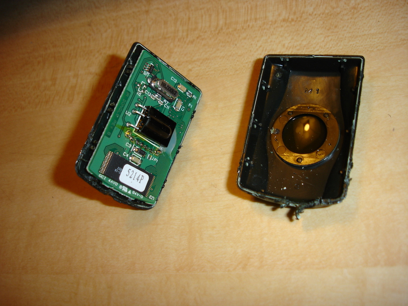
- DVD-ROM Drive - I had already done this, and it's not related to this case exchange whatsover, but it's worth mentioning. I had one of the original Thompson DVD-Rom drives, and when the Samsung 616T mod became public, I decided to do it. Since I now had a standard-looking DVD-ROM drive, it mounted more easily in the new case since it has side screw holes, and also has the correct front bezel. Good pictures of it are here.
Case and Motherboard
The new case is considerably larger than the existing Xbox case, so there's plenty of room to fit things. Mounting the motherboard took a little planning to decide on where to put it. The screw holes for a standard ATX/MicroATX Mobo don't line up at all, so the option of simply screwing it in place is obviously out of the question.
Most of the time the simplest solution is the best one. In this case, it's to take the bottom of the original Xbox (black plastic) and mounting IT inside of the case, and then mounting the motherboard onto it using its original screw holes. To do this I had to saw off the front and back "lips" of the xbox, and ditching the metal RF material all together. The motherboard and power supply fit perfectly.
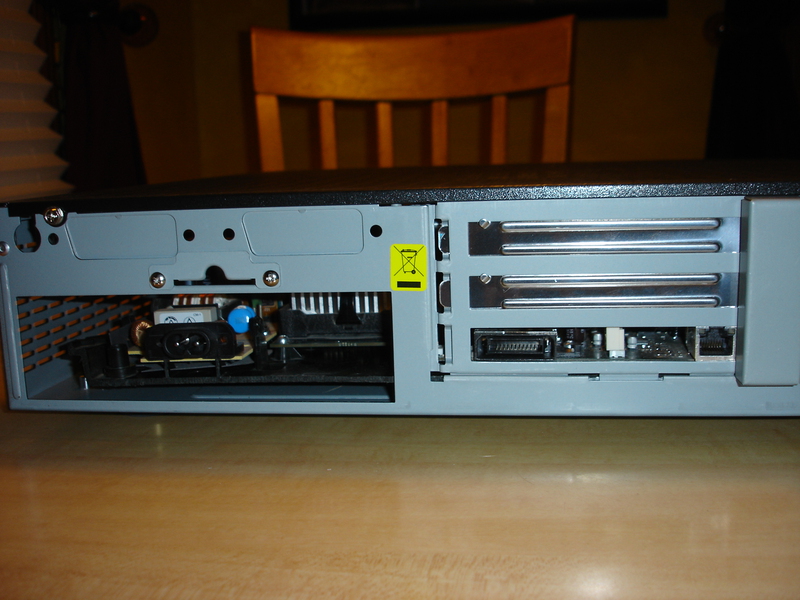
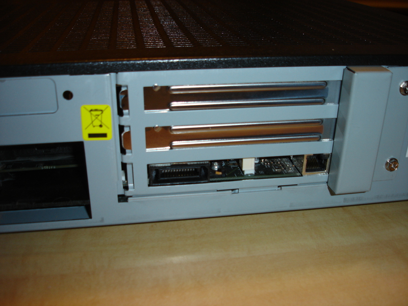
I did this in such a way so that the Video and Ethernet connectors on the xbox sit right with the bottom horizontal PCI slot in the case. The motherboard and plastic had to be raised slightly to do this, so I installed the screw-in case standoffs on top of each other (two high) to get it to the proper height.
If I had the original Xbox HDTV cables, I would have done this differently and recessed everything a bit and put female RCA plugs on the case so you can use standard RCA cables. Since I have the new style with the cables built in, I did it the way I did.
Installing DVD-ROM, Hard drive
This is obvious. They fit right in to the front of the case where a hard drive and optical drive are intended.
Power Button Connection
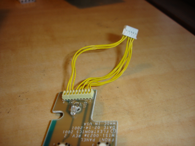
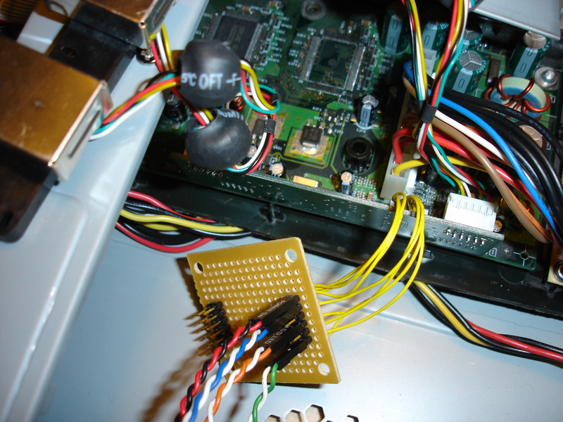
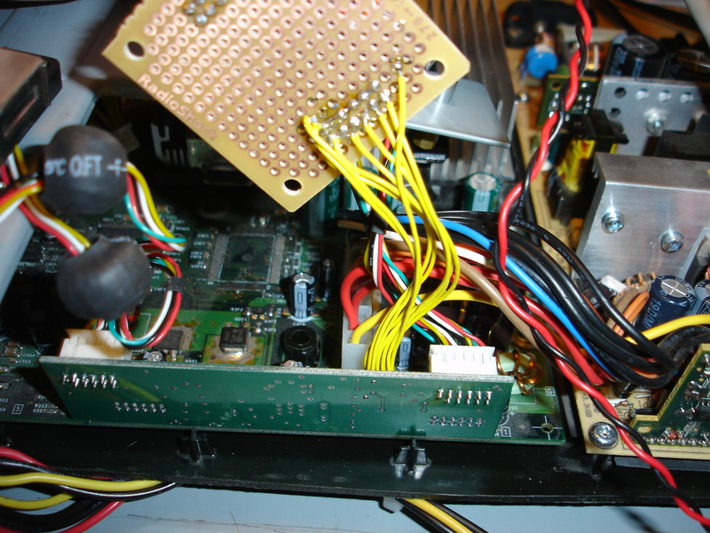
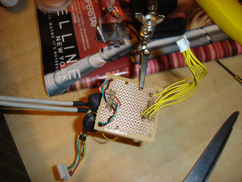
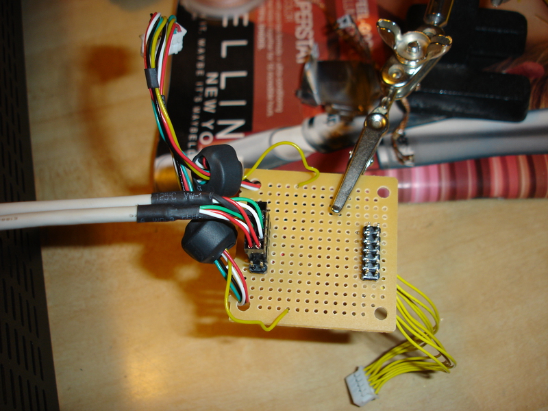
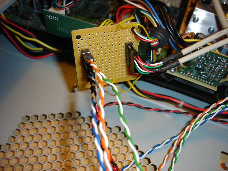
Since the original Xbox power connectors are on their own little PCB with two switches, two LED's, a board had to be made to make it fit with the PC case. Sticking with the Keep It Simple, Stupid thinking, I opted have the board be able to connect to standard PC case connectors via header pins. These pins are the exact same size as you'd find on the back of an IDE Hard drive, as well as the LPC header pins used for most mods. I had a few sets of these laying around, so that was a perfect fit.
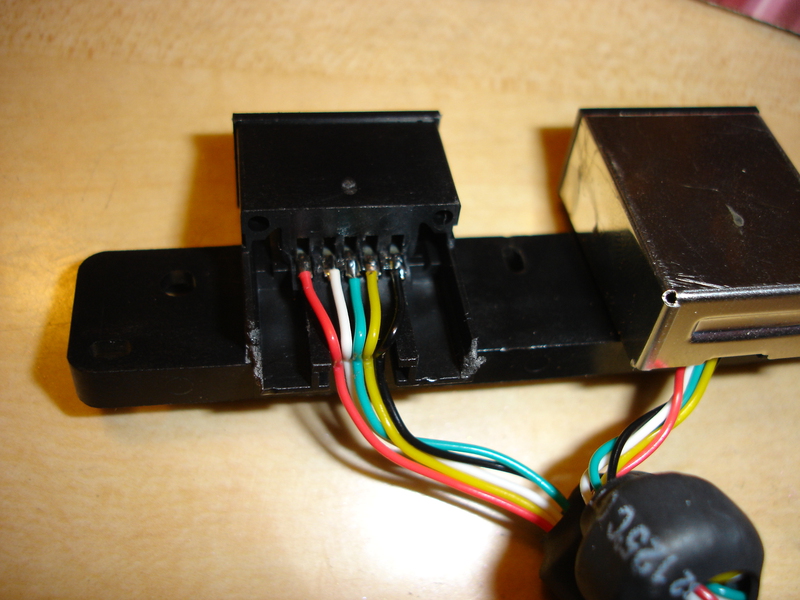
I used the original yellow cable that connects to the front buttons (2x5 pins). I traced out which pin is what, and then detached each yellow wire from the front panel PCB and soldered them onto the board above.
Power/Eject PCB Pinout:
- 1 - Ground
- 2 - Power Switch
- 3 - Ground
- 4 - Eject Switch
- 5 - LED2
- 6 - LED2
- 7 - LED1
- 8 - LED1
- 9 - Nothing
This view is from the BACK of the 2x5 connector (the side with the wires coming out/the holes facing AWAY from you):
| X | 8 | 6 | 4 | 2 |
| 9 | 7 | 5 | 3 | 1 |
Here's possibly an easier way to read this:
| N/A | LED1 | LED2 | Eject SW | Power SW |
| Nothing | LED1 | LED2 | Ground | Ground |
The ground is shared by both Eject and Power switch, as well as the middle prong of each LED.
X is the hole w/ no wire. These numbers jive with the numbers on the PCB, labeled 1 and 9.
I don't know a ton about electronics, so I decided to guess that I can power the case's built in LED's by using any of the four possible LED power sources. So I did this, and it works fine (so far!) The ground of course shares the same ground as the others.
LCD & LCD-MOD Details, Specs, Installation
It was a bit difficult to find the proper information, so I'll put the sources and the info I have here all in one spot.
The info I found was speaking of the Aladdin XT chip that has a parallel bus built in, but it's the same as the LCD-MOD pinouts, pretty much.
Sources. I don't know which was first, but it's all effectively the same info:
- X-S Thread - Aladdin LCD?
- X-S Thread w/ pix - Aladdin XT LCD Working Elitely
- AXT 4064 with LCD in action!
- CFAH2004A-YMC-JP LCD Data Sheet
Here are the pinouts. They're nearly 1:1 in order, so it's nice and simple. The CFAH2004A-YMC-JP supports either a 4 or 8-bit bus, so my assumption is that DB0 - DB3 are if you are using 8-bit, and DB4 - DB7 are for 4-bit. As I said earlier, I dont know a ton about this stuff, but that makes sense to me! :)
| LCD-MOD | CFAH2004A-YMC-JP | Description |
| GND | Vss | Ground |
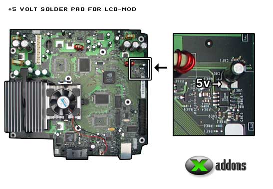
| VDD | Vdd | 5V Power * |
| VEE | Vo | Contrast/Operating Voltage |
| RS | RS | Register Selector |
| R/W | R/W | Read/Write |
| E | E | Chip Enable Signal |
| D4 | DB4 | Data Bit 4 |
| D5 | DB5 | Data Bit 5 |
| D6 | DB6 | Data Bit 6 |
| D7 | DB7 | Data Bit 7 |
| LEDA | A | LED+ (Backlight Only) |
| LEDK | K | LED- (Backlight Only) |
* 5V power note - A wire needs to be soldered for this. This link shows where to get 5v from your mobo ([3]):
Before you wire everything up, my LCD has a backlight so some calculations must be done to know what resistance to set. According to one of the sources above, the calculation is this. Here's a quote from one of the forum posts above:
Resistor = (5V - forward voltage drop)/current

the backlight voltage drop and normal operating current can be found in the
datasheet for your display. eg if voltage drop was 3.6V and you wanted 70mA
of current

Resistor = (5V - 3.6V) / 0.07A = 20 Ohm
***just an example, use your own values here!***
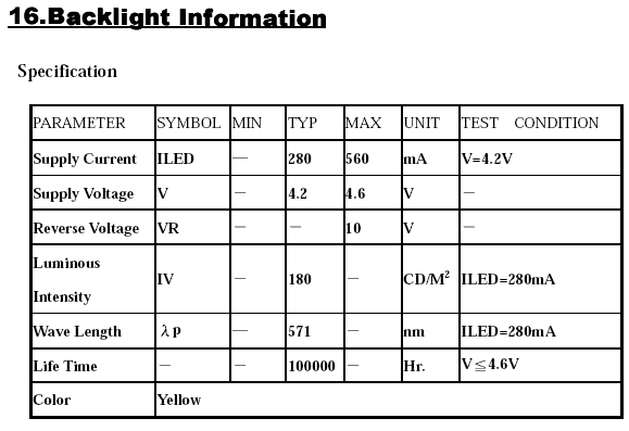
For my CFAH2004A-YMC-JP LCD, here are the backlight specs found in its PDF manual:
- Current = 280mA - 560mA
- Voltage = 4.2V - 4.6V
..And the calculation is:
- Typical (280mA): (5V - 4.2V) / 0.28A = 2.85714286 Ohm
- Max (560mA): (5V - 4.2V) / 0.56A = 1.42857143 Ohm
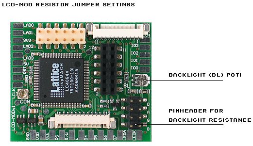
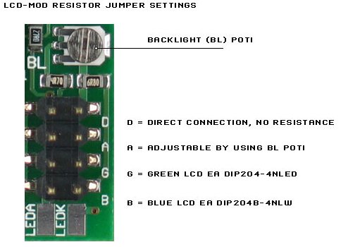
So we need a resistor between 1.42 Ohm and 2.85 Ohm. To be safe, I'm going to start with a 2.85 Ohm. Unfortunately this is out of the range of the POT on the LCD-MOD, which supports 4.7 Ohm - 104.7 Ohm. So, I had to purchase a seperate resistor.
Here's a mirror from the docs for the LCD-MOD which shows details:
Compleded Pictures
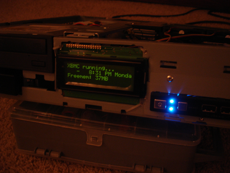
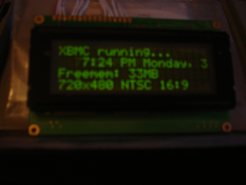
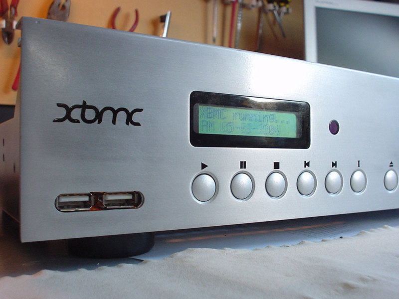
The LCD is installed and works perfectly. It should be brighter, however.
IR Wiring & USB Ports
My personal requirements to get this working the way I want are:
- All 4 Xbox controllers must be usable
- Two front USB ports in case must be usable. USB Hub is used to accomplish
- DVD Playback dongle. Must be hardwired
- Xbox must be able to be turned on/off with IR remote. Via X3IR.
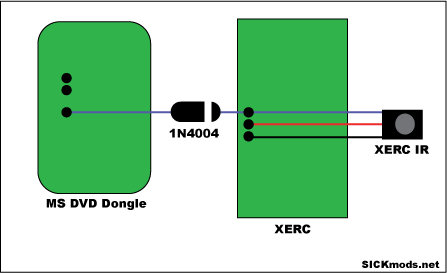
- X3IR and DVD Dongle must share same IR Eye
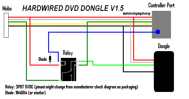
Putting all of this together, this means that the Hardwired DVD Dongle tutorial must be used, but instead of the Dongle, a USB hub will be there. Using a 5V relay, if a controller is in port 4, the Hub/DVD Dongle/Front USB are bypassed. When port 4 Controller is removed, all is back to normal. Since 4 controllers inserted is rare, in almost all cases it will work "normally".
Here was how I intended to have it be wired:
                 +--------------+
                 | Motherboard  |
                 |(Port 4 Wires)|
                 +--------------+
                        |
                    +-------+
                    | Relay |
                    +-------+
                    |       |
       +-------------+      |
       |   USB Hub   |      |
       |4 add'l ports|      |
       +-------------+      |
        |       |   |       |
 +--------+   +--------+   +------------+
 |  DVD   |   | Front  |   | Controller |
 | Dongle |   | USB x2 |   |   Port 4   |
 +--------+   +--------+   +------------+
Here are some diagrams that others made that I inteded to use as a guideline to get this working:
I wired everything up as above, but I couldnt get it to work. Either there was something wrong with my relay, or I was just too stupid to figure it out. I simply couldn't get it to work, so instead I hardwired controller port 4 directly to a 4 port USB hub. The hub then has the DVD dongle hardwired to it, the 2 front USB ports, and then controller port 4. In this scenario, an xbox controller WITHOUT memory card slots in it (a usb hub) should work. "Standard" controllers won't work, but something like a steering wheel or arcade stick should work.
Here's how it ended up looking:
           +--------------+
           | Motherboard  |
           |(Port 4 Wires)|
           +--------------+
                  |
       +-------------------------+
       |         USB Hub         |
       |      4 add'l ports      |
       +-------------------------+
        |       |   |         |
 +--------+   +--------+   +------------+
 |  DVD   |   | Front  |   | Controller |
 | Dongle |   | USB x2 |   |   Port 4   |
 +--------+   +--------+   +------------+
Front USB Connectors
I opted to convert controller 3 and 4 into the front USB connectors that already exist on this case. As with the Power connectors, the same sized header pins work perfectly. I pulled one of the pins out to match the key notch in the USB front panel connector and soldered it onto the same test PCB as above.
To do all of this, I need the female USB header that originally connects to the controller ports. I took a pair of the controller ports out, removed the metal covering, and de-soldered the wires. After this, I connected them to the appropriate pins that match the case's USB connectors.
X3IR and DVD Dongle Eye
One main reason I used the X3IR as opposed to a less expensive IR solution is because it's programmable. The default of Display for on, and 0 for off weren't to my liking. I intended to use the standard RCA "power" code to turn it off/on. From a learning remote, I beleive that to be CF0D23. This unfortunately conflicts with my TV. Instead, I used a non-standard rca "VCR1" code on that remote, which was C785A3. I also changed the default keypress time for power off from 1000ms to 200ms, to match the "on" function.
I couldn't find the correct way to get the IR eye to be shared for both, so I have two IR eyes in the system. The eye for the X3IR is so tiny that it was no problem fitting it behind the main window next to the LCD. The DVD dongle eye is behind the hole in the case where the IR is intended to be.
Similar Projects & More Pictures
Larger pictures of everything shown on this page, as well as larger versions may be found here:
Clean Custom "XBMC" Case This one is far more "custom" than mine, and looks about as nice as can be:
DirecTV Case Transplant
Transplanted into a smaller-than-xbox DirecTV case:
DVD Player case transplant Fairly clean case, minus Xbox logo (my opinion)
